Scope
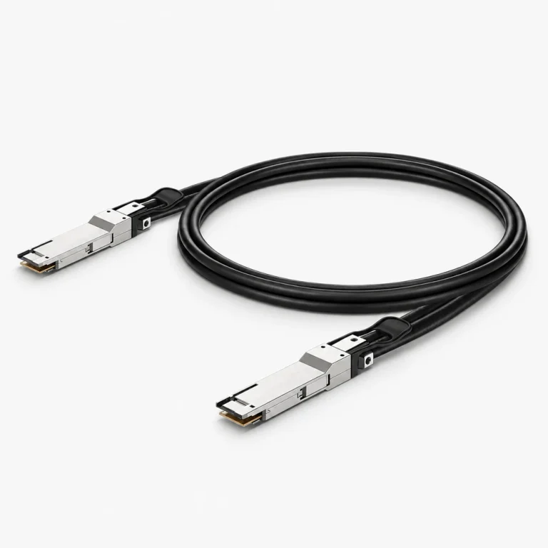
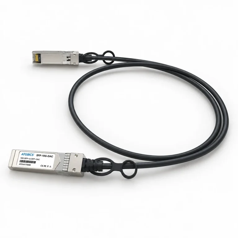
Breakout requirements depend on the parent port, the child-side interfaces, lane mapping, and supported equipment behavior.
Request preparation
List the parent and child devices, breakout arrangement, required lengths, quantity, and whether a specific coded or branded reference is mandatory.
Technical parameters and selection boundaries
Published configurations differ by manufacturer and exact part number. These are selection dimensions, not one combined specification.
| Parameter | Documented example or choice | Verify for this request |
|---|---|---|
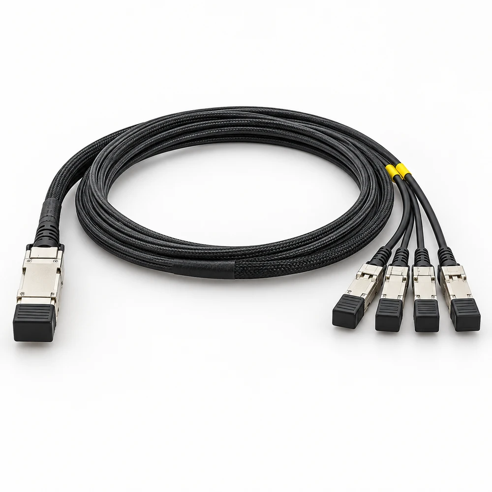
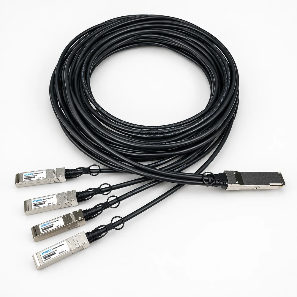
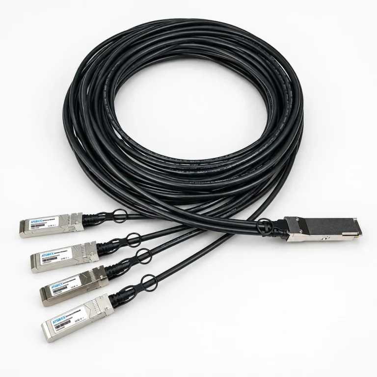
| Breakout topology | The reviewed FS passive assembly connects one 100G QSFP28 port to four 25G SFP28 ports. | The upstream host must support the required split-port mode. A mechanical connector match alone does not enable breakout operation. |
| Cable reach | Up to 5 m in this specific FS copper-assembly document. | Maximum reach belongs to the selected cable design and hosts; it is not a universal limit for copper, optical or active breakouts. |
| Case temperature | 0 to +70 °C in the recommended operating table. | Use cable-end case conditions and the host thermal requirements, not room temperature alone. |
| Supply voltage | 3.13–3.47 V; 3.3 V typical. | These recommended operating values are distinct from absolute maximum ratings. |
| Power dissipation | 0.1 W maximum in the FS table. | Endpoint versus whole-assembly scope is not stated in this table. Confirm the port budget and exact supplied design rather than generalizing the value. |
| Characteristic impedance | 90–110 ohms, 100 ohms typical. | This is the cable’s documented electrical characteristic; it does not establish compatibility with every 100G port. |
| Propagation and skew | Maximum delay 4.5 ns/m; intra-pair skew 10 ps; pair-to-pair skew 50 ps. | Retain the different units and measurement scopes. These are not whole-network latency guarantees. |
| Operating humidity | 5–85% relative humidity in the same operating table. | Confirm environmental requirements for the complete system. |
Standard configurations and project options
| Configuration area | Documented option | Project decision |
|---|---|---|
| Length and branch plan | Select total length and specify the downstream port for each branch. | Provide a port map and desired labels; drawing and branch lengths need confirmation for the actual assembly. |
| Host identification | The FS sheet describes a two-wire I²C interface for the EEPROM signature. | Provide both host brands, models and firmware; any coding option or compatibility claim needs configuration-specific confirmation. |
Representative models and configurations
Examples illustrate real product variation. A listed manufacturer or model is not a statement of our stock, authorization, or confirmed availability.
| Manufacturer / series | Published configuration | Important scope |
|---|---|---|
| ATGBICS ET7402-25DAC-1M-C | Brand catalog SKU for its Edgecore-compatible 1 m passive QSFP28-to-four-SFP28 configuration. | ATGBICS-branded compatibility reference, not an Edgecore-manufactured part or authorization claim. The separate FS electrical table above must not be assigned to this SKU. |
| FS 100G-to-4×25G passive breakout range | QSFP28 to four SFP28; documented copper reach up to 5 m. | Series configuration example, not a complete ordering code. Obtain the length-specific SKU and host qualification. |
Applications and procurement context
- Use a documented breakout topology to connect a supported higher-rate switch port to four lower-rate endpoints. Confirm lane mapping, downstream rates, split-port configuration, cable routing and exact host support before ordering.
Compatibility, current supply, lead time, origin, and acceptance documents must be confirmed for the actual order.