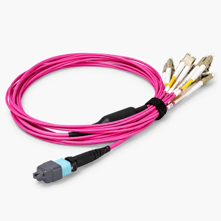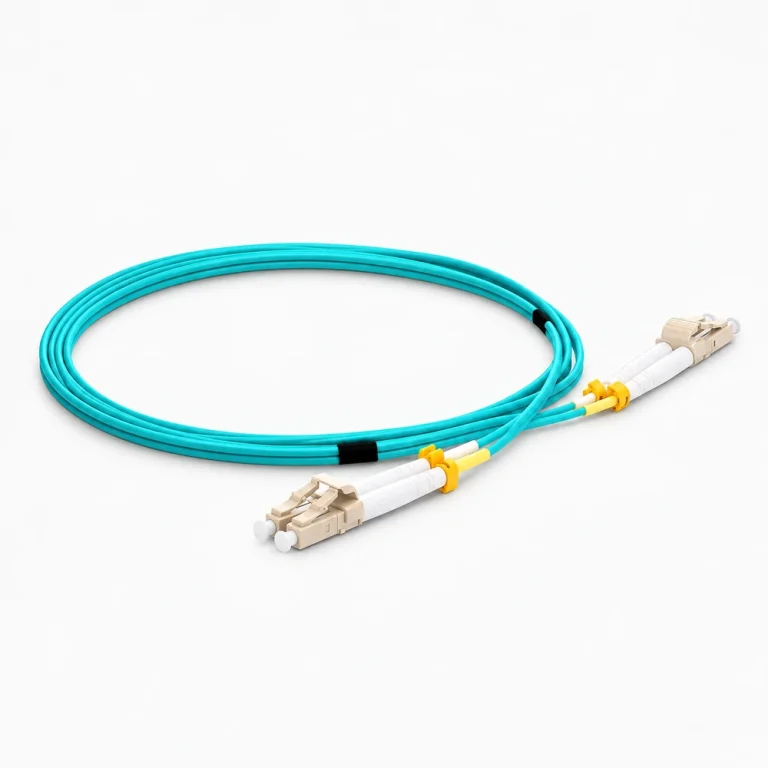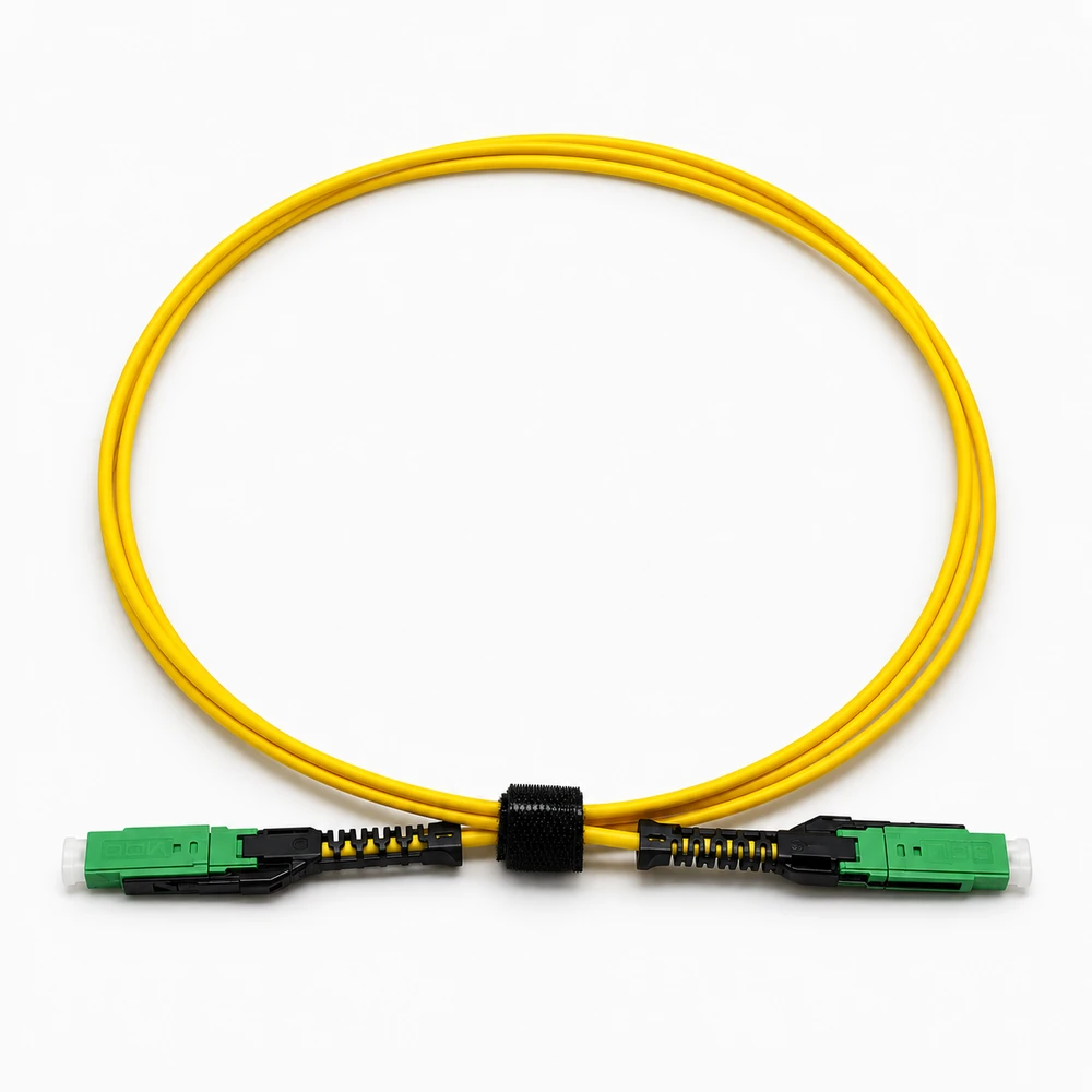
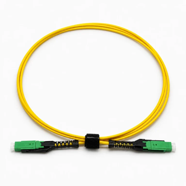
Specify both ends of the link
An MDC assembly should be described as a complete optical path rather than by one connector name. State the mating interfaces and the system where the assembly will be used.
Information needed for quotation
- Connector types and both endpoints
- Fiber type, polarity, and fiber count
- Length, jacket, routing, labeling, and packaging
- Quantity and the inspection or documentation requested
Compatibility boundary
Connector format, polarity, fiber specification, panel arrangement, and equipment support are separate checks. Preserve any approved drawing or complete manufacturer reference.
Technical parameters and selection boundaries
Published configurations differ by manufacturer and exact part number. These are selection dimensions, not one combined specification.
| Parameter | Documented example or choice | Verify for this request |
|---|---|---|
| Fiber and duplex construction | FS documented MDC examples use duplex OS2 9/125 micrometre fiber, grade G.657.A1. | Confirm the fiber grade and optical path; the interface name does not itself specify single-mode or multimode fiber. |
| Connector ends and polish | MDC-to-MDC and MDC-to-LC configurations are listed with UPC-to-UPC polish. | Specify the connector on each side. MDC, SN and CS must not be treated as mechanically interchangeable. |
| Jacket and cable diameter | The inspected MDC range specifies PVC (OFNR) and a 2.0 mm cable diameter. | This differs from the 1.6 mm SN entry in the same document. Confirm jacket and fire requirements for the installation. |
| Minimum bend radius | 10 mm in the inspected FS assembly sheet. | Use the limit only for the named construction; verify installation, pulling and repeated-flex requirements separately. |
| Insertion and return loss | The MDC entry lists insertion loss no more than 0.3 dB and return loss at least 50 dB. | Do not apply the 0.2 dB SN/CS/LC entry to MDC. Request the supplied assembly acceptance test and complete link loss budget. |
| Fiber attenuation | 0.4 dB/km at 1310 nm; MDC 0.3 dB/km at 1550 nm in this document. | These are fiber-length terms, distinct from connector insertion loss. Confirm both measurement wavelength and total routed length. |
| Thermal limits | MDC operating temperature: −10 to +70 °C; storage: −20 to +70 °C. | The limits belong to this supplier construction and are not inferred from the connector manufacturer alone. |
| Polarity and optical-link scope | The sheet gives A (Tx) to B (Rx) polarity and a 400G 2 km example with OSFP-400G-2FR4. | Match the actual transceiver optical interface. The cable connector does not independently guarantee a link rate or distance. |
Standard configurations and project options
| Configuration area | Documented option | Project decision |
|---|---|---|
| Requested length | Separate 1 m and configurable-length MDC-to-MDC listings are documented. | Provide installed route length, service slack and length tolerance; confirm the actual finished configuration. |
| MDC-to-LC end arrangement | The range includes MDC UPC to LC UPC Uniboot in both 1 m and requested-length versions. | Use this only when each endpoint requires that connector; identify each port and polarity in the RFQ. |
| Fiber and fire-rating selection | The referenced items are OS2 with PVC (OFNR). | LSZH, plenum, multimode or other constructions need their own confirmed product specification. They are not implied by these example catalog IDs. |
Representative models and configurations
Examples illustrate real product variation. A listed manufacturer or model is not a statement of our stock, authorization, or confirmed availability.
| Manufacturer / series | Published configuration | Important scope |
|---|---|---|
| FS #130963 | 1 m; US Conec MDC UPC to MDC UPC; duplex OS2; PVC (OFNR); 2.0 mm. | Catalog ID from the retained document. Confirm current configuration and orderability; a Family reference photo is not a SKU identification label. |
| FS #130967 | Requested-length MDC UPC to MDC UPC; duplex OS2; PVC (OFNR); 2.0 mm. | Configuration entry; requested length and acceptance limits require confirmation. |
| FS #130968 | 1 m; US Conec MDC UPC to LC UPC Uniboot; duplex OS2; PVC (OFNR); 2.0 mm. | Mixed-end assembly. Specify both equipment endpoints before accepting an alternative. |
Applications and procurement context
- Use MDC assemblies for patching designs that explicitly require the MDC interface. Gather equipment and transceiver identity, both connector ends, polarity, cable route, fiber type and the installed channel loss budget.
Compatibility, current supply, lead time, origin, and acceptance documents must be confirmed for the actual order.